Hi All
I would like some guidance on a Pye P75A I am trying to repair. Despite some determined reading and application of brain-power, I can't seem to find the cause of the problem :@. Therefore, I'm throwing myself on the mercy of this forum.
After reforming the reservoir/smoothing electrolytic, replacing the output Tx (o/c primary on the original one) and replacing that capacitor, I can get stations on MW and LW, but nothing on SW - just a quiet hiss across the dial. Reading around led me to believe that the local oscillator was at fault, and this was confirmed using an oscilloscope - I got a nice sinusoidal waveform from the grid of the triode section of the frequency changer on MW and LW, but nothing when switching to SW. This set employs two oscillator coils, one for MW/LW and one for SW.
I narrowed my focus immediately to the SW local oscillator circuit, which, once you get past the wavechange switching, is pretty straightforward. Continuity checks through the switch and the coils (L5 - Manufacturer's Service Sheet) appear to be satisfactory. I tested the associated capacitors (C10 and C11) in situ for leakage and also capacitance (using the capacitance function on a Digital Mulitmeter) - they seemed OK (not sure how accurate the capacitance function is supposed to be on a DMM). Kind of as expected, really, as these are mica jobs. Resistor R4, which feeds the anode of the triode section on SW, is rather high (17.5kΩ - +17%), but bridging this to bring it to spec had no effect.
Anyhow, if you're still reading, I have a few specific questions I'd like to ask:
1) When I checked the local oscillator function using the oscilloscope, would applying the probe to the grid of the triode section actually stop oscillation?
2) Was I correct in focussing on the SW oscillator circuitry straight away? For example, I notice the voltage on the screen grid of the frequency changer seems rather low (~70V) - could this affect oscillation of the triode section?
3) Because the LO works on MW/LW, I took this to mean that the components common to all three wavebands (i.e. C16, C12, R6, R23 and C2) were satisfactory. Is this assumption correct?
It did occur to me that the valve (a 6C9) could be at fault. I got a replacement when I went to Golborne in April (thanks Dave T), though this did not remedy the situation (but I have no proof that the replacement was good - it wasn't a new valve).
Anyhoo - I would appreciate any thoughts/answers you might have. Be nice, though, as this is first old radio I've looked at in over 20 years
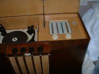
Some piccies attached as a bonus.
[attachment=1178]
[attachment=1179]
[attachment=1180]
I would like some guidance on a Pye P75A I am trying to repair. Despite some determined reading and application of brain-power, I can't seem to find the cause of the problem :@. Therefore, I'm throwing myself on the mercy of this forum.
After reforming the reservoir/smoothing electrolytic, replacing the output Tx (o/c primary on the original one) and replacing that capacitor, I can get stations on MW and LW, but nothing on SW - just a quiet hiss across the dial. Reading around led me to believe that the local oscillator was at fault, and this was confirmed using an oscilloscope - I got a nice sinusoidal waveform from the grid of the triode section of the frequency changer on MW and LW, but nothing when switching to SW. This set employs two oscillator coils, one for MW/LW and one for SW.
I narrowed my focus immediately to the SW local oscillator circuit, which, once you get past the wavechange switching, is pretty straightforward. Continuity checks through the switch and the coils (L5 - Manufacturer's Service Sheet) appear to be satisfactory. I tested the associated capacitors (C10 and C11) in situ for leakage and also capacitance (using the capacitance function on a Digital Mulitmeter) - they seemed OK (not sure how accurate the capacitance function is supposed to be on a DMM). Kind of as expected, really, as these are mica jobs. Resistor R4, which feeds the anode of the triode section on SW, is rather high (17.5kΩ - +17%), but bridging this to bring it to spec had no effect.
Anyhow, if you're still reading, I have a few specific questions I'd like to ask:
1) When I checked the local oscillator function using the oscilloscope, would applying the probe to the grid of the triode section actually stop oscillation?
2) Was I correct in focussing on the SW oscillator circuitry straight away? For example, I notice the voltage on the screen grid of the frequency changer seems rather low (~70V) - could this affect oscillation of the triode section?
3) Because the LO works on MW/LW, I took this to mean that the components common to all three wavebands (i.e. C16, C12, R6, R23 and C2) were satisfactory. Is this assumption correct?
It did occur to me that the valve (a 6C9) could be at fault. I got a replacement when I went to Golborne in April (thanks Dave T), though this did not remedy the situation (but I have no proof that the replacement was good - it wasn't a new valve).
Anyhoo - I would appreciate any thoughts/answers you might have. Be nice, though, as this is first old radio I've looked at in over 20 years
Some piccies attached as a bonus.
[attachment=1178]
[attachment=1179]
[attachment=1180]